The Invisible Leaks: Mastering Thermal Bridging with Precision
Bilal S.
Founder & CEO - BDR
Introduction
Let’s cut through the noise: energy doesn’t ask for permission when it finds a shortcut out of your building. It sees a thermal bridge, whether that is a steel stud, metal fastener, or even a poorly layered insulation joint, all flashing a neon sign that says “Exit Here.” You’re the gatekeeper. Understanding and closing these exits isn’t just good practice; it is the foundation for high-performance, durable, and comfortable buildings.
In the spirit of clarity (and a bit of Hormozi-style straight talk), we’re going to dismantle the myth that good insulation alone is enough. Thermal bridging is the silent saboteur, undermining all that expensive R-value you paid for. Detection is half the battle, and it starts with seeing the invisible.
See the Unseen: The Power of Thermal Imaging
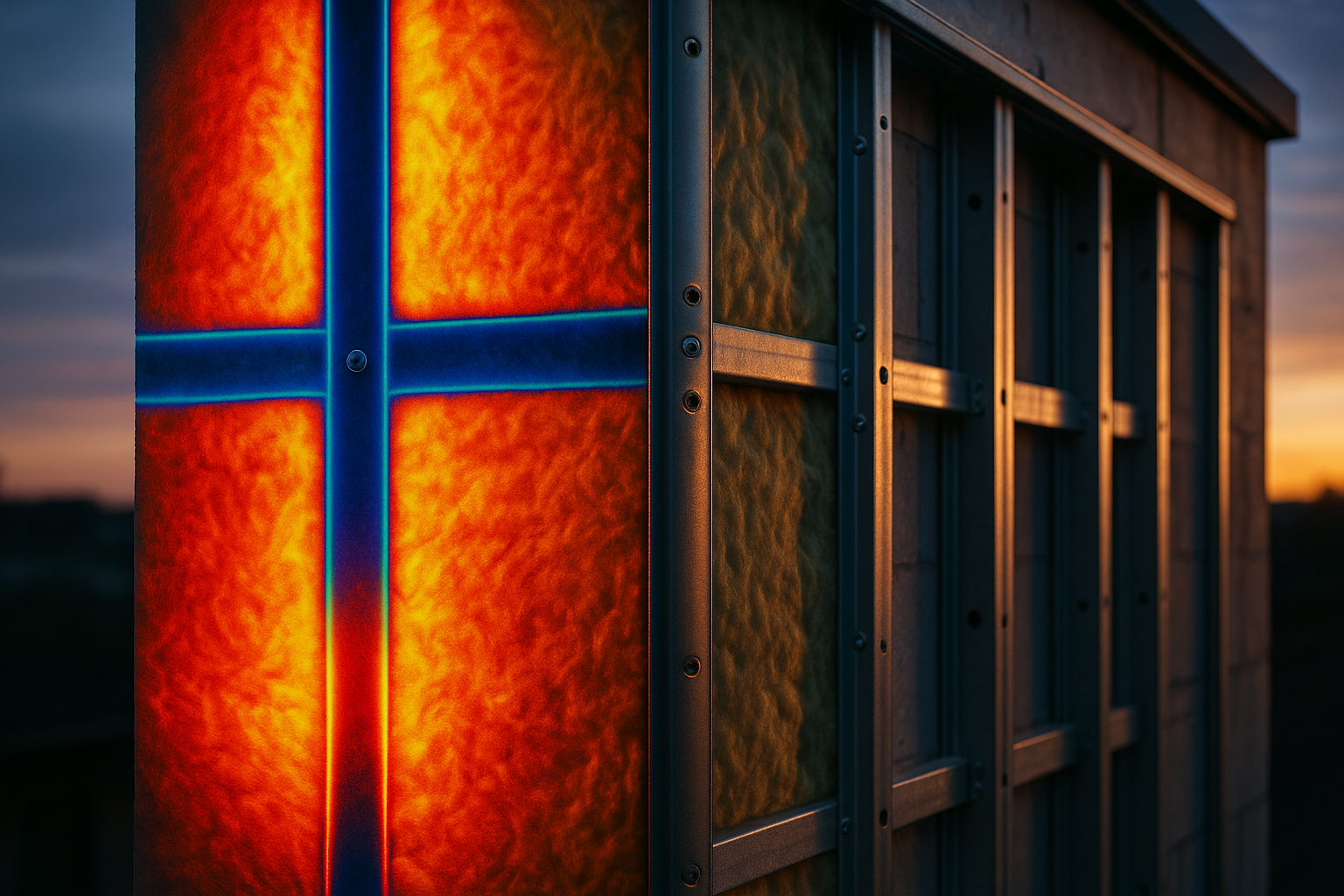
Thermal imaging, also known as infrared thermography, is like giving your buildings X-ray vision. It’s not about guessing; it’s about visualizing the actual, measurable temperature differences on surface materials. This isn’t theory; it’s non-destructive, real-world diagnostics.
But you’re not just after pretty rainbows on a screen. You’re hunting for patterns, such as thermal bridges, insulation defects, unplanned air leaks, and even sneaky moisture hiding where it doesn’t belong.
How do these show up?
- Conduction: Think “hot knife through butter.” Metal fasteners or steel framing; spot the cold lines where they cross insulation.
- Evaporation: That wet spot is cooler, which is no surprise. Moisture evaporates and steals heat energy as it goes.
- Air Leaks: Drafts are temperature swings in disguise. Cracks, gaps, and air infiltration all get exposed if you tune your imaging right.
But imaging isn’t foolproof. Mother Nature loves to meddle. Solar gain, wind, rain, and humidity can mask critical details or send you on a false trail. You want early morning or late night inspections for the real story, and always calibrate for surface emissivity, environmental conditions, and reflected radiation.
Detection isn’t just eyeballing. Clustering algorithms like K-means, or methods such as Threshold-Based Clustering (TBC), slice your images into hot spots and cold spots mathematically. You want objectivity, not gut feelings.
Limits? Of course:
- Not enough temperature difference between indoors and outdoors? Your clues vanish.
- Moisture or solar influence? Risk of false positives.
- Some problems need backup, such as blower doors or moisture meters, to get the full picture.
Bottom line: The building doesn’t lie. But it takes sharp tools, as well as sharper interpretation, to sort the signal from the static.
The Hard Numbers: U-Value Calculations Demystified
Here’s where most people get tripped up: U-value isn’t an abstract metric. It’s a practical measure of your building envelope’s heat transfer efficiency; in other words, how much “leakage” you’re willing to tolerate.
The concept is simple: Lower U-value equals better insulation.
But the calculation? That’s where it gets nuanced:
- Analytical Formulas: Consider radiative, convective, and conductive heat transfer. Input your surface temperatures, material emissivities, wind speeds, and air temperature gradients.
- Thermal Imaging Enhanced Estimation: Use temperatures from your thermal scans, layered with real environmental data, to approximate U-values for trouble spots.
- Heat Flux Sensors: Stick to the literal. Measure the energy going through a surface, then cross-reference with temperature readings for truer accuracy.
- Numerical Modeling: When the assembly gets complex (think multifaceted junctions), finite element analysis is your friend.
But here’s the Hormozi point: accuracy is in the details. Surface material emissivity, wind speed, time of day, solar exposure; any variable can tip the scales. Thermal images need proper segmentation or you’re measuring the noise, not the signal.
The state-of-the-art approaches? Use clustering and (if you dare) machine learning to segment and analyze your images, running multiple parallel U-value calculations (U1, U2, U3...) and averaging for consistency.
Measurement is not magic; it is math underpinned by insight. It is only as good as your assumptions and as robust as your tools.
Model Before You Mend: Software as Your Second Brain
If you try tackling complex thermal bridges without digital simulation, you’re flying blind. Modeling software brings structure to intuition; it is the difference between tinkering and targeted intervention.
THERM
Go-to for 2D analysis. It breaks down wall, roof, and window sections for steady-state heat transfer, showing you exactly where the thermal short-circuit is in plane view. But remember, world isn’t flat; neither are your heat leaks.
When 2D slices won’t cut it, step up to 3D. Metal fasteners, odd angles, and roof assemblies are all in play. Want to see the cumulative impact of a grid of connectors in three dimensions? HEAT3 lays it bare.
WUFI®
Thermal losses are only half the problem; moisture is the other ticking time-bomb. WUFI blends heat and moisture transport over time (hygrothermal simulation), letting you predict condensation risk and durability. This includes not only present-day leaks but also tomorrow’s mold patch.
WINDOW & HEATING 7
Focus on window glazing, or run steady-state test simulations in a lab? These tools round out your understanding, from U-values to solar gain, to pinpointing the weak links.
Energy-RCI Calculator
Adjust your insulation specs to compensate for measured losses. If you’re not factoring in thermal bridging penalties, you’re padding your numbers on paper, not in reality.
Case-Closed: Lessons from the Field
Roofing Assemblies: Tiny Fasteners, Huge Impact
Metal fasteners are minuscule, yet they can obliterate up to 14.5% of your effective R-value in a single swoop. If you use high-density patterns, that can rocket to nearly half your insulation rendered pointless. Worse, you pay for every inch of wasted efficiency.
Remedy?
- Adhesive attachment systems: No punctures, no shortcuts for heat. More upfront cost, yes, but energy bills shrink fast to compensate.
- Layered insulation with staggered joints: Interrupt the linear bridge pathway. Add a cover board to shield fasteners, mitigate radiant heat exchange, and smooth temperature profiles.
Steel-Framed Walls: The Conductor’s Dilemma
Steel is strong, but it’s also a highway for heat loss. Expect a 40% minimum haircut to your R-value if you ignore the bridge.
Better play?
- Continuous insulation wraps the steel outside, breaking the bridge.
- Swap out metal clips with composite standoffs or structural foam.
- Use spray foam directly applied for air-tight, moisture-resistant barriers.
- Design walls with air gaps and minimize insulation between studs; don’t give heat a direct path.
Remember: If you fix the thermal bridge but let moisture or air leaks slide, you’re trading one problem for another. Full-system thinking matters.
Retrofits: Out-With-the-Old, In-With-the-Advanced
Why not leapfrog legacy problems?
- ICFs and SIPs integrate airtight, continuous insulation by design.
- Vacuum Insulated Panels pack massive R-values in slim packages. However, be mindful of new potential bridges such as fasteners and panel edges.
- Use diagnostics such as IRT, measured U-values, and hygrothermal software to target intervention rather than relying solely on blanket upgrades.
Takeaways
Thermal bridging is the invisible drain on comfort, durability, and performance, and, like any weak link, it will determine your building's real-world outcomes. The best in the business blend hands-on diagnostics, mathematical analysis, and smart modeling to see the problem, size it up, and solve it permanently.
You don’t need to guess. Arm yourself with the right data, the right tools, and a relentless commitment to closing every loophole energy can escape from. That is how you build better, smarter, and for the long haul.
References
-
Albatici, R., Tonelli, A. M., & Chiogna, M. (2015). A comprehensive experimental approach for the validation of quantitative infrared thermography in the evaluation of building thermal transmittance. Applied Energy, 141, 218–228.
-
Balaras, C. A., & Argiriou, A. A. (2002). Infrared thermography for building diagnostics. Energy and Buildings, 34(2), 171-183.
-
Building Envelope Thermal Bridging Guide. (2016). BC Hydro Power Smart. https://www.bchydro.com/content/dam/BCHydro/customer-portal/documents/power-smart/builders-developers/building-envelope-thermal-bridging-guide-1.1.pdf
-
National Research Council Canada. (2023). Thermal losses because of fasteners for R-26, R-31 and R-36 test roof assemblies using #14 fasteners. The NRCA Roofing Manual: Membrane Roof Systems—2023.
-
Singh, M., Gulati, R., Srinivasan, R. S., & Bhandari, M. (2016). Three-Dimensional Heat Transfer Analysis of Metal Fasteners in Roofing Assemblies. Buildings, 6(4), 49. https://doi.org/10.3390/buildings6040049
-
Taylor, T. J. (2020). Eliminating Fastener Thermal Bridging in Low Slope Roofs: Energy Efficiency Savings versus Installation Costs. Open Journal of Energy Efficiency, 9, 94-110. https://doi.org/10.4236/ojee.2020.92007